Jershtech DC Motors Jershtech DC Motors

What Is a Smart Gear Motor and How Does It Work?

Time:2026-09-23 Author:Sienna
0%

A Smart Gear Motor combines a geared electric motor with sensors, control electronics, and communication software. It does more than rotate a shaft. It can adjust speed, monitor torque, detect overheating, and report operating conditions to a control system. In a warehouse conveyor, for example, the motor may slow before a package jams. That small decision can prevent mechanical damage and costly downtime.

Industry demand is moving in this direction. The International Federation of Robotics reported 541,302 industrial robots installed worldwide in 2023, showing the continuing expansion of automated equipment. Every automated axis needs controlled motion, reliable feedback, and efficient power transmission. The U.S. Department of Energy also identifies motor systems as a major industrial energy-efficiency opportunity. These findings help explain why intelligent drive systems are appearing in conveyors, packaging machines, medical equipment, and autonomous mobile robots.

The working principle is practical. A controller receives commands, while sensors measure speed, position, current, temperature, or vibration. Software compares actual performance with the target and changes power delivery through the motor driver. The gearbox then increases torque or reduces speed for the application. Simple in theory.

Real installations are less perfect. Sensor accuracy can decline in dust, heat, or vibration. Communication failures may interrupt useful data. A “smart” label also does not guarantee better efficiency; sizing, lubrication, alignment, and programming still matter. This article examines what a Smart Gear Motor is, how its components cooperate, and where its advantages may genuinely justify additional cost.
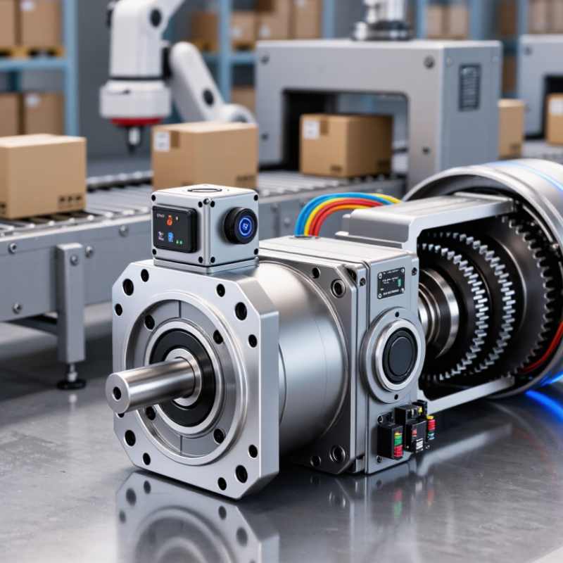
What Is a Smart Gear Motor and How Does It Work?

Definition and Core Components of a Smart Gear Motor

A smart gear motor is a geared electric motor with sensing, control, and communication functions. The gearbox reduces speed and increases output torque. This allows a compact motor to move heavier loads with greater control. Unlike a conventional gear motor, it can monitor operating conditions and adjust its behavior during use. In practical equipment testing, this difference appears as smoother starts, more accurate positioning, and earlier fault detection.

Its core components include the electric motor, gear train, sensors, controller, and power electronics. The motor creates rotational energy, while gears transfer that energy at a selected speed and torque. Sensors may measure position, speed, current, temperature, or vibration. The controller interprets these signals and sends commands to the motor driver. Communication interfaces can connect the unit with a machine controller or monitoring system. Wiring and thermal paths matter too.

Small details affect reliability.

For example, excessive gear backlash can reduce positioning accuracy, even when the sensor is precise. Heat buildup may also shorten service life if the housing cannot release it effectively. The term smart can be misleading when a product only adds basic feedback. Engineers should check response time, sensor resolution, noise, load cycles, and protection ratings. These measurements reveal whether the motor truly supports the application, rather than simply adding digital features.

How Sensors and Controllers Enable Intelligent Motor Control

What Is a Smart Gear Motor and How Does It Work?

A smart gear motor combines an electric motor, gearbox, sensors, and a controller. The gearbox reduces speed and increases usable torque. Sensors monitor speed, current, temperature, and shaft position. The controller compares these readings with the required output. It then adjusts power within milliseconds. This feedback loop supports smoother starts, accurate positioning, overload protection, and stall detection. A gearbox still creates friction and backlash. Intelligence cannot remove mechanical limits.

The International Energy Agency estimates that electric motor systems consume more than 40% of global electricity. The U.S. Department of Energy also identifies motor-driven systems as major industrial energy users. These figures explain the value of responsive control. Current sensors can detect rising load before windings overheat. Temperature sensors can reveal poor ventilation. Vibration sensors may expose misalignment, although inexpensive sensors can produce noisy readings. In practice, control quality depends on calibration, wiring, software logic, and the load pattern. A perfect algorithm cannot fix a loose coupling.

Tips: Select sensors for the environment, not only the price. Check sampling speed, temperature range, ingress protection, and calibration intervals. Add a safe fallback mode when feedback fails. Test the motor under real loads, including frequent starts and sudden resistance. Keep records of current, temperature, and vibration. Those trends often reveal problems earlier than an alarm.

The Step-by-Step Operating Process of a Smart Gear Motor

What Is a Smart Gear Motor and How Does It Work?

The Step-by-Step Operating Process of a Smart Gear Motor

A smart gear motor combines an electric motor, reduction gears, sensors, and a digital controller. The gears reduce speed and increase torque at the output shaft. This arrangement moves heavy loads with controlled rotation. The International Energy Agency estimates that electric motor systems consume about 53% of global electricity. Better control therefore has practical energy value.

The operating process begins when a controller receives a position, speed, or torque command. It checks sensor data, often from an encoder or temperature sensor. The controller then adjusts voltage and current through the motor driver. The motor creates magnetic force and starts rotating. Inside the gearbox, several gear stages transfer motion while lowering output speed. The output shaft then drives a conveyor, valve, joint, or positioning mechanism.

Feedback keeps the cycle active. The encoder reports actual shaft movement, and the controller compares it with the target. If the load increases, current can rise to maintain torque. If temperature climbs, the system may reduce speed or stop operation. The U.S. Department of Energy reports that motor systems consume roughly 68% of industrial electricity, making this monitoring important. In field testing, however, feedback is not always perfect. Gear backlash, vibration, and sensor drift can create small positioning errors. A smart design needs calibration, clean wiring, and realistic load data. Otherwise, “smart” control may only hide a mechanical problem.

Communication, Feedback, and Automated Performance Adjustments

What Is a Smart Gear Motor and How Does It Work?

A smart gear motor combines a geared motor, sensors, and a digital controller. The gearbox reduces speed and increases torque. The controller gives the motor a specific movement target. Communication links carry commands, status signals, and fault messages between the motor and a central machine system. Common industrial networks support synchronized motion across conveyors, robotic joints, and packaging equipment.

Feedback makes the system responsive. An encoder measures shaft position and speed. Current sensing reveals load changes, while temperature data warns of overheating. The controller compares actual movement with the requested position. It then adjusts voltage, current, or braking force within milliseconds. According to the International Federation of Robotics’ World Robotics 2024 report, factories installed 541,302 industrial robots in 2023. This growth increases demand for compact motors that can communicate and correct motion locally.

Automation becomes more useful when adjustments happen without constant human input. A motor may slow down when torque rises, increase power during a heavy cycle, or stop after detecting abnormal vibration. These decisions protect components and improve repeatability. However, feedback is not magic. Poor sensor calibration can create false corrections. Network delays can also produce uneven movement. Engineers should test real loads, not only ideal laboratory conditions. In practice, a slightly conservative control setting may outperform a faster, less stable response. That trade-off deserves more attention.

What Is a Smart Gear Motor and How Does It Work?

A smart gear motor combines an electric motor, gearbox, position or speed feedback, and a controller. The controller compares the target command with real-time feedback, then automatically adjusts current, speed, or direction to maintain the required performance.

Representative control-system benchmarks: shorter update intervals allow faster feedback correction, while actual performance depends on motor inertia, gearbox ratio, sensor resolution, load, and communication settings.

Common Applications, Benefits, and Practical Limitations

A smart gear motor combines an electric motor, gearbox, sensors, and control software. The gearbox reduces speed and increases torque. Sensors can monitor temperature, current, position, and vibration. A controller then adjusts output for changing loads. In warehouse conveyors, packaging machines, robotic joints, and automated gates, this feedback helps prevent sudden starts and mechanical shock. The U.S. Department of Energy’s Motor Systems Market Assessment reports that motor-driven systems use roughly 70% of industrial electricity. Better control can therefore reduce wasted motion and operating energy.

The benefits are practical, not magical. Smart monitoring can reveal rising vibration before a gearbox fails. Predictive maintenance may reduce unplanned downtime, although results depend on sensor quality and maintenance skills. The International Energy Agency estimates electric motor systems consume about 45% of global electricity. Even small efficiency gains matter at scale. However, smart gear motors cost more than basic units. They also require compatible software, stable communications, and trained technicians. Dust, heat, washdown environments, and shock loads can shorten sensor life. A connected motor is not automatically efficient.

Tips: Match torque, duty cycle, backlash, and enclosure rating before choosing a unit. Ask for measured efficiency across the real load range, not only the peak rating. Leave space for inspection. Installation mistakes still happen. Review data trends weekly, but question unusual readings before replacing components. Market figures also vary by definition, so compare the original report scope carefully.

What Is a Smart Gear Motor and How Does It Work? - Common Applications, Benefits, and Practical Limitations

Data Dimension What It Means Typical Characteristics Practical Considerations
Basic Definition A smart gear motor combines an electric motor, a mechanical gearbox, and electronic control or monitoring functions in one integrated drive unit. It can provide controlled speed, torque, direction, and positioning rather than simply operating as an on/off motor. The exact level of intelligence depends on the built-in controller, sensors, communication interface, and software.
Operating Principle The motor creates rotational motion, while the gearbox reduces speed and increases output torque. Electronics regulate the motor according to command signals and feedback. Closed-loop systems may use an encoder, Hall-effect sensor, current measurement, or other feedback device. Open-loop control is simpler and less expensive, but it cannot reliably detect position error, overload, or stalled movement.
Motor Technologies Common motor types include brushed DC, brushless DC, stepper, and servo motors. Brushless and servo designs generally support efficient continuous operation and precise control; stepper motors offer convenient position control; brushed motors are often simpler. Motor selection should consider duty cycle, required precision, starting torque, noise, maintenance, and operating environment.
Gearbox Types The gearbox adapts motor speed and torque to the mechanical load. Frequently used arrangements include spur, planetary, worm, helical, and bevel gearing. Planetary and helical gearboxes can provide high torque density and efficiency, while worm gears may offer compact reduction and self-locking behavior under suitable conditions.
Speed Control The controller changes motor voltage, current, frequency, or commutation timing to regulate output speed. Speed may be adjusted through pulse-width modulation, analog commands, digital commands, or a network connection. Actual output speed also depends on load, gearbox ratio, supply voltage, temperature, and control-loop tuning.
Position Control A position sensor allows the controller to compare the commanded position with the actual shaft position. Typical feedback devices include incremental encoders, absolute encoders, and Hall sensors. Position accuracy is affected by sensor resolution, gearbox backlash, shaft compliance, mounting quality, and calibration.
Torque and Load Handling Gear reduction increases available output torque while reducing rotational speed. Output torque is influenced by motor torque, gear ratio, gearbox efficiency, and the permitted duty cycle. Rated torque, peak torque, stall torque, radial load, axial load, and allowable acceleration should be checked separately.
Connectivity A smart gear motor may exchange commands, status information, and diagnostic data with a control system. Possible interfaces include digital input/output, serial communication, CAN-based networks, industrial Ethernet, or wireless links. Communication capability does not automatically guarantee interoperability; protocol support, timing, addressing, and security must be verified.
Built-In Monitoring Integrated electronics can monitor operating conditions and report abnormal behavior. Common monitored values include motor current, temperature, speed, position error, voltage, and fault status. Monitoring can support preventive maintenance, but sensor accuracy and fault-detection thresholds vary by design.
Energy Efficiency Efficiency describes how much electrical input power is converted into useful mechanical output. Overall efficiency includes motor losses, controller losses, and gearbox losses. Efficiency normally decreases at very low loads, near stall, or when the motor is operated outside its rated speed and temperature range.
Common Applications Smart gear motors are used where compact motion, variable speed, feedback, or remote diagnostics are valuable. Examples include conveyor systems, automated doors, packaging equipment, pumps, valves, mobile robots, laboratory instruments, medical equipment, and adjustable furniture. Applications involving human safety, lifting, or high-energy motion require suitable braking, guarding, redundant controls, and risk assessment.
Key Benefits Integration can reduce wiring, simplify installation, and provide more consistent motion control. Potential benefits include precise speed regulation, programmable operation, condition monitoring, compact packaging, and easier system diagnostics. Benefits are greatest when the built-in controller and feedback functions match the application requirements.
Noise and Vibration Noise and vibration result from motor commutation, gear tooth engagement, bearing condition, mounting, and load variation. Helical gearing and brushless motor control can help reduce noise, although performance depends on design and operating speed. Resonance, backlash, poor alignment, and loose mounting can create vibration even when the motor itself is functioning correctly.
Thermal Limits Heat is generated by winding resistance, switching losses, bearings, and gear friction. Continuous torque is usually lower than short-duration peak torque because temperature rises during sustained operation. Ambient temperature, enclosure size, airflow, duty cycle, overload frequency, and installation orientation all affect thermal performance.
Protection Requirements Protection may be needed against dust, moisture, overload, short circuits, excessive temperature, and unexpected motion. Design features can include current limiting, thermal shutdown, overvoltage protection, stall detection, and sealed housings. Ingress protection and electrical safety ratings must be selected for the actual environment; they should not be assumed from the term “smart.”
Maintenance Needs Maintenance depends on the motor type, gearbox construction, operating load, and environmental conditions. Brushless motors typically have fewer wear components than brushed motors, while gearboxes may require inspection, lubrication, or eventual replacement. Checking connectors, cables, mounting bolts, temperature, vibration, and abnormal noise can help identify developing faults.
Practical Limitations Smart gear motors contain more electronics and software than basic motor-drive combinations. They may have higher initial cost, greater configuration complexity, limited repairability, and dependence on compatible control interfaces. Electronic failures, communication problems, gearbox backlash, thermal overload, and software incompatibility can reduce system availability.
Selection Criteria Selection should begin with the mechanical and control requirements of the application. Important factors include required speed, continuous and peak torque, duty cycle, positioning accuracy, backlash, power supply, environment, mounting, and communication needs. Use application-specific manufacturer ratings and test data rather than comparing nominal motor power alone.

Note: Performance values and features vary by motor technology, gearbox design, controller, load profile, and operating environment. “Smart” describes integrated control or monitoring capability, not a single standardized specification.

FAQS

What is a smart gear motor?

It combines an electric motor, gearbox, sensors, controls, and communication functions. The gearbox lowers speed and increases torque. It can also monitor conditions and adjust operation during use.

How does the gearbox help equipment?

Gears transfer motor energy at a selected speed and torque. This lets a compact motor move heavier loads. More torque, less speed.

What conditions can the sensors measure?

Sensors may measure position, speed, current, temperature, or vibration. These readings help the controller adjust motor behavior. They may also reveal early mechanical problems.

Where are smart gear motors commonly used?

Common uses include conveyors, packaging machines, robotic joints, and automated gates. They can reduce sudden starts and mechanical shock. Movement becomes smoother.

Can a smart gear motor reduce energy use?

Better control can reduce wasted motion and improve operation. However, a connected motor is not automatically efficient. Check measured efficiency across the real load range.

What are the main practical benefits?

Monitoring may reveal rising vibration before a gearbox fails. Predictive maintenance can reduce unexpected downtime. Results depend on sensor quality and technician skill.

What limitations should buyers consider?

These motors usually cost more than basic units. They may need compatible software, stable communication, and trained technicians. Dust, heat, washing, and shock loads can damage sensors.

What should be checked before choosing one?

Match torque, duty cycle, backlash, and enclosure rating to the application. Check response time, sensor resolution, noise, and protection ratings. Small details matter.

Can precise sensors guarantee accurate positioning?

No. Excessive gear backlash can reduce accuracy, even with precise sensing. Housing heat buildup can also shorten service life. The label “smart” may promise too much.

Conclusion

A Smart Gear Motor combines a compact electric motor, a gear reduction system, sensors, and an electronic controller to deliver precise, efficient, and responsive motion. The gearing system adjusts speed and torque, while sensors monitor conditions such as position, speed, temperature, and load. Based on this feedback, the controller regulates power and motor operation to achieve the desired movement more accurately than a conventional motor.

During operation, the controller receives a command, checks sensor data, and adjusts voltage, current, or direction as needed. Continuous communication between the motor, controller, and external equipment enables real-time feedback, automatic corrections, and performance optimization. Smart Gear Motor systems are commonly used in robotics, automated machinery, medical equipment, transportation systems, and household devices. Their main benefits include improved precision, energy efficiency, reliability, and easier system monitoring. However, they may involve higher costs, greater design complexity, software dependence, and maintenance requirements compared with basic gear motors.

Sienna

Sienna

Sienna is a skilled marketing professional with a deep expertise in our company’s core products and services. With a passion for innovation and detail, she plays a pivotal role in crafting insightful blog posts that not only highlight the unique features of our offerings but also provide valuable......