 Jershtech DC Motors
Jershtech DC Motors
Jershtech DC Motors
Choosing a DC Motor Controller is not simply a matter of matching voltage and current. Real installations reveal the harder questions. Will the controller survive repeated starts? Can it manage stall current? Does it remain cool inside a small, dusty enclosure?
Dr. John M. Miller, an electric-drive specialist, states, “The electric motor is only as good as the control system that drives it.” That principle guides this practical introduction. A reliable controller must fit the motor, power supply, load profile, and operating environment. A 24-volt motor may need far more than 24 volts during acceleration. Its brief current surge can damage an undersized controller. Measure it.
These ten tips examine the details that product pages often hide. They cover rated voltage, continuous and peak current, PWM control, speed feedback, braking, protection features, thermal performance, and electromagnetic interference. They also consider wiring length, enclosure ventilation, and maintenance access. Small details matter.
Look beyond the headline rating.
For example, a controller rated at 20 amps may support that current only with adequate cooling. A sealed box can quietly turn a safe installation into a thermal problem. I have seen designs fail because engineers selected by nominal current alone. That mistake is easy to repeat.
The right choice should be documented, tested, and reviewed against real operating conditions. Datasheets help, but bench testing exposes weaknesses. No controller is universally best. The most dependable option is the one that matches the complete system, not just the motor label.
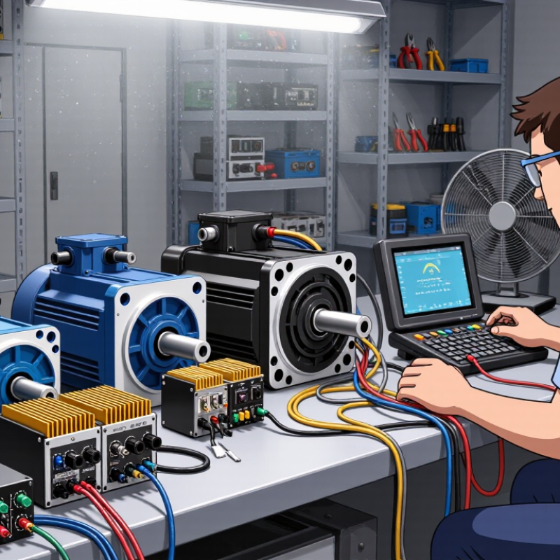
A controller must match the motor’s real operating envelope, not only its label. A 12–48 V motor system may experience battery charging peaks, wiring losses, and regenerative voltage spikes. Check the controller’s operating range and transient limit. IEC 60034-1:2022 separates continuous ratings from short-time conditions, which matters during acceleration and repeated starts. The U.S. Department of Energy reports that motor-driven systems consume about 70% of U.S. manufacturing electricity. Small rating mistakes can therefore create significant heat and wasted energy.
Tip: Record the motor’s nominal voltage, continuous current, peak current, and rated speed. Compare these values with the controller’s thermal specifications. Continuous current should exceed the measured running current, especially inside a warm enclosure. Stall torque deserves more attention. At zero speed, current can rise sharply, while airflow remains almost absent. A controller with enough peak-current capacity can protect the motor during brief starts, but excessive stall duration may still damage windings.
Tip: Estimate torque from the load, gearbox ratio, and acceleration time. Do not rely on speed alone. A 3,000 rpm motor may fail to start a heavy conveyor, despite appearing powerful. NEMA MG 1-2024 emphasizes that motor performance depends on load and operating conditions. A clean spreadsheet can still mislead. Measure current with the actual load, then review the result at the hottest expected temperature. Speed feedback also matters; open-loop control may drift under changing friction or battery voltage.
Choose at least 1.5 times the motor’s continuous current. For a 10 A motor, select 15 A or more. For short peaks, allow twice the expected maximum current. Check ratings at the real voltage, cooling condition, and duty cycle.
Heavy belts, wheels, or gearboxes can extend startup current. Bench testing may look safe. Repeated starts can reveal hidden heat. Measure temperature near the power terminals under normal load. My earlier running-current estimate was too optimistic.
Use a fuse or current limiter suited to the wiring and battery system. Check protection against voltage spikes and braking energy. Confirm stall, reversing, and acceleration behavior. A larger current rating cannot fix weak connections or poor cooling.
A low setting near 1 kHz can provide strong torque and simple tuning. It may create an audible whine. Higher settings, up to 20 kHz, can reduce audible switching noise. They may also increase heat and switching losses. Measure current and temperature under real load.
Hall sensors provide speed pulses and reliable low-speed feedback. Loose wiring can create false readings. Use twisted or shielded signal wires near power cables. Compare displayed speed with a handheld tachometer. Default pulse settings may be wrong.
Begin with modest acceleration and proportional gain. Add integral action only when steady-state error remains. Too much gain can cause hunting, surging, or hot windings. Test startup, load changes, and ten-minute operation. A heavy belt may expose problems later.
Interpret the enclosure rating alongside cable glands and mounting direction. Dust, water spray, condensation, and heat can reduce practical protection. An enclosure may resist water jets. Poor sealing still creates risk. Inspect the complete installation, not just the housing label.
Identify where regenerative energy will go during deceleration. A braking resistor or controlled DC bus may be necessary. Check resistor duty cycle, stopping frequency, and overvoltage protection. For EMC, verify testing conditions and cable recommendations. Listen during acceleration and light-load operation. Cable routing may be the real fault.
Choosing the right DC Motor Controller begins with clearly defining the motor’s operating requirements. Confirm the system voltage, typically within a 12–48 V range, along with continuous current, stall torque, and required speed. The controller should provide sufficient capacity for real operating conditions, with a recommended margin of about 1.5 times the continuous current and twice the expected peak current. PWM frequency, usually between 1 and 20 kHz, should suit the motor and application, while Hall sensors or other feedback devices can improve RPM regulation and performance.
Thermal protection and system reliability are equally important. Evaluate operation at a 40°C ambient temperature, provide suitable heat sinking, and select a controller with dependable overcurrent protection. Before installation, also review electromagnetic compatibility requirements such as IEC 61800-3, the necessary IP protection rating, regenerative braking behavior, and acceptable acoustic or electrical noise levels. A careful match between motor specifications, controller capacity, feedback features, safety functions, and environmental conditions will support efficient and stable long-term operation.
